1. Main use:
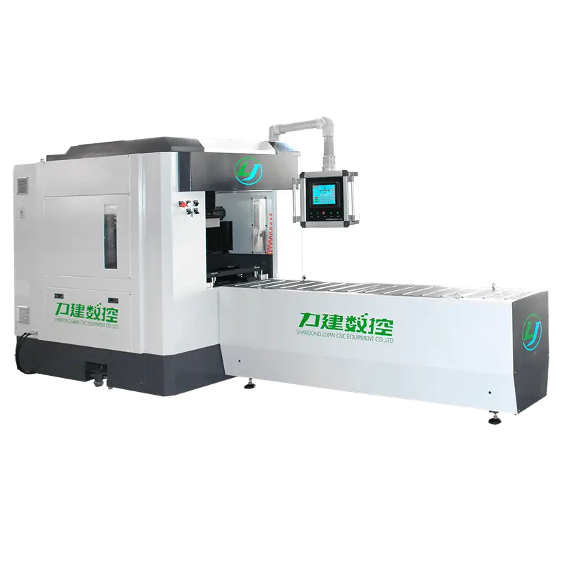
The main function of the CNC Busbar Milling Machine is to perform arc machining on the end of copper busbar. It is mainly used for milling angle and arc angle of copper and aluminum busbars with thickness of 4-16mm and width of 30-200mm. It has simple structure with convenient use.
2. Control mode:
The electrical control is controlled by 5-axis CNC system.
The feeding and cutting of copper busbar are completed through the start-up of spindle motor and servo motor.
The clamping or loosening of cutter is completed by pneumatic control.
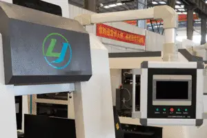
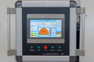
The two-axis CNC automatic control system is adopted, and a 10.4″LCD is equipped, which can display the working state of the machine tool. It has the functions of storing according to the input work number, calling the counting of workload, displaying and communicating, simulating processing, as well as online manual programming.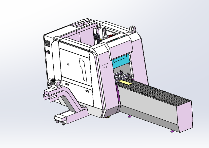
3. Machine tool structure, advantages and operation characteristics:
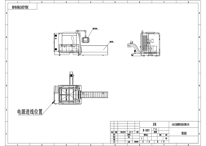
The machine primarily consists of a lathe bed workbench, gantry, slide rails, servo motors, power head, cylinders, fixture devices, a pneumatic system, a CNC system, protective covers, and other key components.
Utilizing a gantry-type mechanical structure, it features a fully welded steel plate box design. This construction delivers excellent rigidity while keeping the bed lightweight, thereby meeting the demands of robust spindle cutting and ensuring sensitive feed response from moving parts.
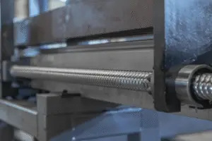
For precision motion, the machine employs high-precision ball screws and linear guides. Specifically, it incorporates high-load, large-size guides in its selection, which enhances overall rigidity, reduces vibration and noise, improves workpiece quality, and guarantees both high accuracy and efficiency.
At its core, the spindle integrates a high-precision, high-speed milling unit driven by a variable-frequency motor and synchronous belt for seamless speed variation.
This configuration provides a simple and reliable transmission, requires no lubrication, allows convenient cooling, and ensures high installation precision along with exceptional cutting speed.
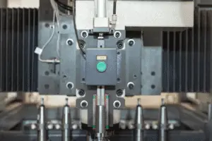
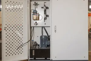
Regarding workpiece handling, a three-point positioning system ensures accurate placement. Subsequently, a combined pneumatic and hydraulic clamping mechanism secures the workpiece, offering stable, impact-free speed, reliable clamping force, and easy adjustability.
To ensure durability, the longitudinal (Y-axis) transmission and guide system includes an organ-type protective cover, effectively preventing flying dust from contaminating the equipment.
Additionally, the lathe bed houses a six-station inline tool magazine, making the replacement and storage of commonly used tools straightforward.
Beneath the machine body, a chip collection groove and trolley are installed. This design not only facilitates the gathering of metal chips but also saves floor space, all while maintaining simplicity and reliability.
In terms of functionality, the machine includes a non-resettable automatic working hour accumulator as well as a resettable production counter.
For cutting operations, the machine uses formed tool shearing with BT40 standard tool holders. These ensure simple tool changes, strong rigidity, and high precision. Furthermore, the six-station inline magazine can automatically switch tools based on busbar thickness.
Finally, the machine comes equipped with a water circulation system and an added automatic chip removal system. Throughout its design, it incorporates well-known domestic and international components, guaranteeing long service life and assured quality.
6 milling cutters (standard configuration: 4, 5, 6, 8, 10, 12), one set of attached tools, one set of instructions and one set of certificate.