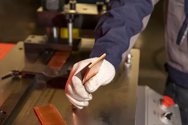
Copper busbars play an essential role in electrical systems, ensuring efficient power distribution. When bending copper busbars, accuracy is crucial to maintain both functionality and safety. This article covers the essential calculations for copper busbar bending, providing a clear understanding of the factors involved.
Importance of Copper Busbar Bending
Copper busbars are primarily used to conduct electricity efficiently, thanks to copper’s excellent electrical properties. However, bending copper busbars correctly is necessary to avoid stress concentrations that could lead to mechanical failure or reduced conductivity. Proper bending also ensures that the busbar fits well within the overall system design.
Factors Influencing Copper Busbar Bending
1. Copper Material Properties
Copper’s material properties play a significant role in determining how the busbar reacts to bending. The following aspects must be considered:
- Yield Strength: The stress level at which copper begins to deform permanently.
- Modulus of Elasticity: This determines the stiffness and elasticity of copper during bending.
- Tensile Strength: The maximum stress copper can endure before breaking.
Understanding these properties helps in calculating the appropriate bend radius and angle for copper busbars, ensuring they maintain their structural integrity after bending.
2. Bend Radius and Angle Calculations
The bend radius is a critical factor in busbar bending. It refers to the minimum radius at which the copper busbar can be bent without causing damage. Typically, the radius should be at least 8 to 10 times the thickness of the busbar. A smaller radius increases the risk of cracks and material failure.
The bend angle, usually ranging from 45° to 180°, determines the extent of the curve. To calculate the busbar length before the bend, use the formula:L=360θ×2π×R
Where:
- L is the length before the bend
- θ is the bend angle in degrees
- R is the bend radius
This formula ensures the busbar’s length matches the required dimensions and that the bend angle is accurately maintained.
3. Stress and Strain Considerations
Stress and strain calculations help ensure that copper busbars withstand bending forces without permanent deformation. The bending stress can be calculated using the formula:σ=IM×c
Where:
- σ is the bending stress
- M is the applied moment
- c is the distance from the neutral axis to the outer surface
- I is the moment of inertia of the cross-section
This calculation ensures that the copper busbar can handle the stress induced by bending without breaking or losing functionality.
Best Practices for Copper Busbar Bending
1. Using the Right Tools
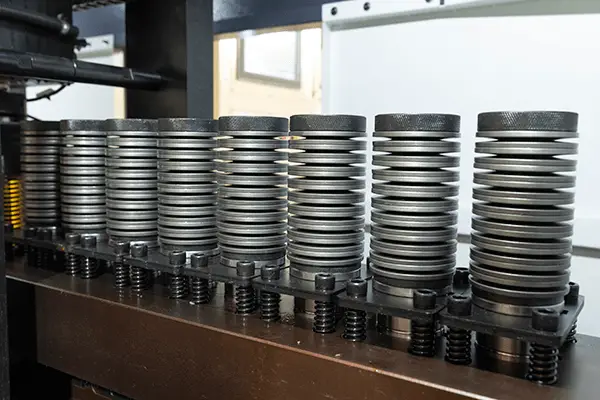
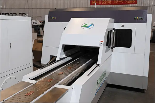
Specialized equipment, such as CNC bending machines, is essential for achieving accurate bends. These machines allow precise control over the bend radius and angle, reducing the risk of errors that can compromise the busbar’s performance.
2. Ensuring Accuracy with Quality Control
After bending, it’s crucial to verify that the busbar meets the required dimensions. Measuring the bend radius, angle, and length ensures compliance with design specifications. Additionally, testing the busbar for electrical conductivity guarantees that it will function optimally in the system.
Conclusion
Copper busbar bending is a precise process that involves several important calculations. By understanding the material properties, calculating the correct bend radius and angle, and ensuring proper stress distribution, manufacturers can produce copper busbars that are both functional and durable. Adhering to best practices and utilizing the right tools will help maintain the quality of the busbars and optimize their performance in electrical systems.